
Fuel Cell System Introduction
The fuel cell system is the most basic and core part of a fuel cell vehicle. The biggest difference between fuel cell vehicles and power battery vehicles is the use of hydrogen and oxygen to generate electricity. The fuel cell system is mainly composed of an electric stack, a fuel processor, a power conditioner, and an air compressor. Each system component has its own unique key technologies, of which the stack technology is the most critical.
Fuel cell stack. In order to meet the requirements of a certain output power and output voltage, fuel cell (FC) cells are usually combined in a certain way to form a fuel cell stack, and corresponding auxiliary equipment (BOP, Balance Of Plant) is configured. Under the control of the battery control unit, the normal operation of the fuel cell is realized, which together constitute the fuel cell system. A fuel cell system used as a vehicle power source is called a fuel cell engine. The fuel cell stack is the core of the fuel cell engine. The BOP keeps the stack running continuously and safely. The fuel cell engine auxiliary system mainly includes an air compressor, a fuel cell humidifier, a hydrogen circulation pump, a pressure regulator, and a system control unit. The typical structure of a hydrogen-fueled fuel cell engine is shown in the figure.
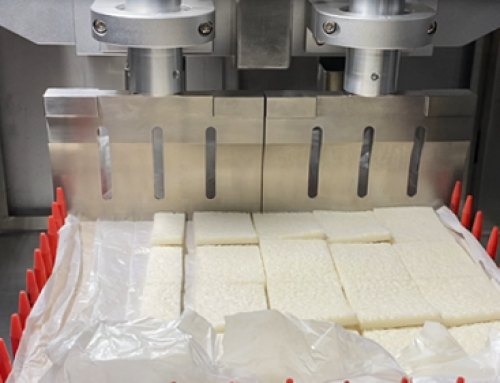
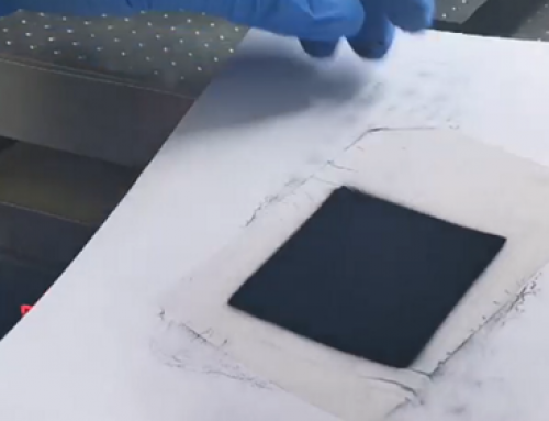
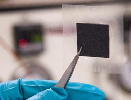
Fuel cell stacks are the main components of fuel cell systems, including electrodes, proton exchange membranes (PEM), bipolar plates, gas diffusion layers (GDL), and end plates. Among them, the electrode, PEM and GDL are integrated into a membrane electrode (MEA), which is the main component of the stack. The electrode is a thin layer of pressure with electrical conductivity between PEM and GDL, and is where the electrochemical reaction occurs. PEM is a thin film between the cathode catalytic layer and the anode catalytic layer. It is a hydrogen proton conducting medium. The performance of PEM directly affects the performance of the entire stack. The bipolar plate is used to support the membrane electrode and collect single cell current. All single batteries are connected in series through bipolar plates to provide electric power that meets vehicle power requirements.
Fuel cell system control technology. The durability of the fuel cell is the key to the problem of the fuel cell vehicle, and a large part of the durability is the problem of the control system. A large number of studies have shown that the key factors affecting the life of a fuel cell are: dynamic operating conditions, starting, continuous idle speed, etc. These factors are ultimately determined by system control. Therefore, fuel cell system control technology has become one of the most critical technologies for fuel cells.
The fuel cell control unit in the figure includes an air compressor control module, a fuel cell system control module, and a battery voltage monitoring module. The air compressor control box receives the control signal sent by the fuel cell control module, and sends a feedback signal (such as the speed of the air compressor) to the fuel cell system control module. The fuel cell system control module mainly determines appropriate control parameters according to the various signals received, and communicates with the vehicle management system through the CAN bus. The battery voltage monitoring module is used to monitor the single-cell voltage, and sends a warning signal to the fuel cell control module when the voltage is too low. Through the comprehensive role of the auxiliary system and the control system, the fuel cell system can be operated efficiently, and the most efficient use of energy can be achieved.

